By Bruce Bayne, 3/25/2022
Having a watermaker onboard or not can be an interesting debate. There are numerous posts in online forums on the subject, if you desire going down that rabbit hole. We discussed the subject for some time and decided it was important to be freshwater independent. Meaning that we would never have to plan our stops around water. We had also heard that if purchasing a watermaker, buy the largest capacity watermaker that fits your budget. I’ll add to that…and buy the largest watermaker you can fit on your boat.
We decided to purchase a 30gal/hr 120vac unit from CruiseROWater. The decision wasn’t an easy one, as there are a number of choices. I knew I wanted a kit that used off-the-shelf components, as the drop-in units often use proprietary components that can be difficult to source and expensive to replace. An off-the-shelf watermaker kit made sense, as these systems are usually basic and simple. This meant I could find the parts and repair it myself if and when it needed fixing.
There are some basic choices to be made in selecting a watermaker system. The first is how the unit will be powered, either from the 12V (or 24V) DC system, or 120VAC.
AC systems require either shore power, a generator, or a suitable inverter.
The second choice involves the capacity in gallons per hour, which directly affects power requirements. Overall boat power management must be considered.
Note that some systems are available that use a mechanical pressure amplifier called a Clark Pump to improve efficiency up to 3 times.
Craig Johnston
A very important step not to skip
Before we purchased the watermaker, I needed to know if all the components would fit in the boat and where they would fit, as watermakers are not tiny. A 30gal/hr unit requires two 44” pressure vessels, and I wasn’t sure I had room for two. I certainly didn’t want to purchase two pressure vessels and find out I only had room for one.
Most watermakers have two large components, and various smaller components, hoses, and tubing. The reverse osmosis (RO) pressure vessels are 44” long and about 3” in diameter each. The high-pressure pump that forces the water through the RO membranes has a rather large and heavy 1hp electric motor with a high-pressure pump attached to it. It’s about 10” in diameter and 18” long and weighs about 50 pounds. They each needed a home on our boat.

I usually make cardboard mockups of large things to ensure they will fit in the space intended. I’ve done this with our holding tank and a freshwater tank. This gives me the ability to move the mockup around to find the best fit. In my opinion, this is the single most important step to installing anything that has any size to it. So, I bought some 3” in diameter mailing tubes and cut them to the exact size of the two pressure vessels. I then mocked up the high-pressure pump with some cardboard to simulate its relative sizes.
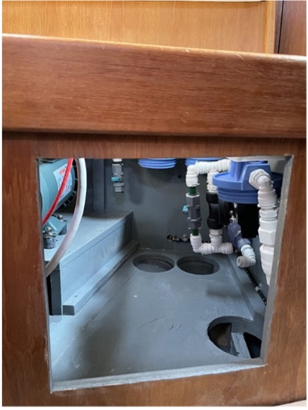
After a bit of trial and error I was able to find a place under the cabinet behind the port settee where both pressure vessels would fit. Normally the pressure vessels are mounted with hardware that sets the two side-by-side. I didn’t have the room to do this, but I did have the room to mount them individually in that space. This would require separate mounting hardware and an extra hose with different hose fittings to connect the two pressure vessels together. I consulted with the manufacturer on this and they said it wouldn’t be a problem.
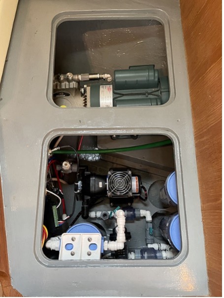
The only place I found where I could mount the high-pressure pump was under the “L” portion of our port settee. There physically was room, but the hull slopes up in that area, so I needed to build a shelf to sit the high-pressure pump on. Once these two components had homes, I was confident they would fit, so I placed the order for the 30gal/hr watermaker.
Installing the components
The instruction manual that comes with this watermaker is quite complete. It details how the components go together, the flow of both salt and fresh water, and how to wire the two pumps. Exactly how it all fits together is determined by the location of each component from one another and the obstacles the hoses and tubing have to go around or through.
After studying the manual, I used Adobe Illustrator to make a drawing of how the components would be connected together within the space I had available for them. I went through several iteration of drawings until I had one that I felt worked best. I now had a drawing that showed each and every valve, elbow, and length of tubing I needed, and how they would fit together.
The kit came with quite a bit of tubing of several sizes and a bag of fittings. I took inventory of the fittings to see if I had the fittings I needed based on my drawing. I was shy a few, so I found a source online to purchase the extra fittings I needed.
It seemed best to install the two largest components first, the pressure vessels and the high-pressure pump, as these could only be mounted in the spaces I identified for them using the mockups, and they were going to take the most time to mount. All the hoses, tubing, filters, and boost pump were small, and I had enough room in the locker to mount them without issue.
Our boat had one access hatch for the “L” portion of the settee. This didn’t give me enough room to mount the high-pressure pump, so I cut a second hatch over the space where the pump was going. I then built a plywood shelf and epoxied it onto the hull. This took a bit of time, but I felt it was necessary for a proper installation of the heavy high-pressure pump.
The high-pressure pump motor has a metal base with four bolt holes to attach it to the shelf. It didn’t come with any vibration dampening mounts, so I found some online that would do the job nicely. These mounts would prevent the motor vibration from transferring to the hull, hopefully keeping the noise from the motor down a bit. Before I mounted the motor, I connected the wiring and pressure relief valve tubing as they would have been difficult to connect once the motor was in place.
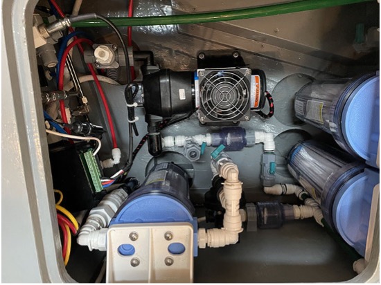
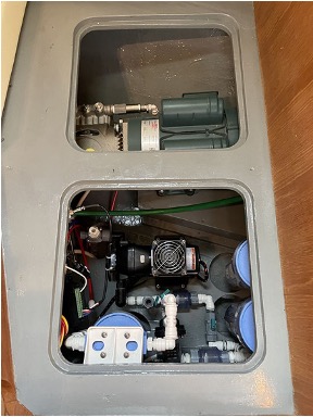
Next, I mounted the pressure vessels under the cabinet. Other than being a tight fit, I was able to get them mounted easily with some help from my wife, Lynette. I also attached the high-pressure hoses and the freshwater tubing at that time so the pressure vessel portion of the install would be complete.
The water flow for the watermaker requires two through hull fittings; one for the seawater intake into the watermaker and one for the waste brine to exit. I already had a through hull for the intake, so I only needed to drill a hole above the waterline and mount a small through hull for the waste brine.
Once the through hull was mounted, I installed the three filter housings and connected the components with the tubing and fittings as per my drawing and the instruction manual. The locker below the settee didn’t have enough headroom to unscrew the filter housings and remove the filters, so I had to cut holes in the floor below the filter housings to allow the housings to be lowered enough to get the filters in and out. Luckily I had about 4” of space between the hull and the floor of the locker. I decided not to mount the boost pump until I had all the tubing installed and the hose from the through hull installed. That way I could place the boost pump exactly where it needed to be to connect to the tubing and hose.
Probably the most difficult task was to snake a ¾” hose from the through hull under the galley sink to the locker where the watermaker was being installed. It was about a 15’ run and required drilling some holes in very inaccessible locations to get the hose installed. At the same time, I wire tied two ¼” tubes that supplied fresh water to the water tanks and sample water to one of the sink foot pump faucets for testing. This way, when I installed the ¾” hose the two tubes came along for the ride. Once the ¾” supply hose was installed I was able to install the boost pump in exactly the correct location to connect to the supply hose.
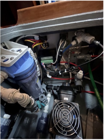
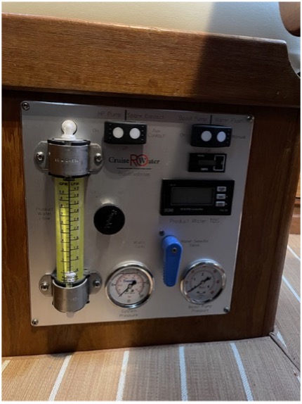
This watermaker has a very nice control panel with everything you need to run the watermaker. I cut a hole in the side of the settee to mount the control panel. Some of the tubing and hoses needed to be attached to the back of the control panel. Once that was done, the liquid side of the watermaker install was finished.
Our watermaker uses both 120vac and 12vdc. I had to add a breaker to each electrical panel and run two sets of wires from the panel to the watermaker control panel. The 120vac is for the high-pressure pump and the 12vdc is for the boost pump. I wired the high-pressure pump into the normal house 120vac panel so I could use the inverter to power the watermaker when the engine was running or hook the Honda generator to the shore power cord to run the watermaker when we weren’t running the engine. That way I had two sources to power the high-pressure pump that were convenient to use.
Commissioning the watermaker
Once the electrical was done it was time to test for leaks and commission the watermaker. We made a short trip out of the marina in Barra de Navidad to be in clear water for the testing. The instruction manual gives clear instruction on commissioning the watermaker, so after reading that portion of the manual, I proceeded to test the watermaker. As soon as both pumps had run for a bit and the air was purged from the system, I increased the pressure to the RO membranes. When the RO membranes had about 800psi of saltwater pressure the watermaker was making about 30gal/hr of fresh water. I then checked for leaks all along the plumbing. Luckily there were no leaks.
Watermakers require frequent freshwater flushes of the membranes when not in use to prevent the buildup of bacteria and organisms. I set an event in my Google Calendar to remind me every three days to switch on the freshwater flush for 3-5 minutes. Some watermakes have a feature to do this automatically. Ours had an option we could purchase, but we decided it was simple enough to do it manually. Less to go wrong in my opinion. Yes, I have to remember, but it’s not the end of the world if I forget one time here and there. If we plan to be gone for an extended period of time, I will just prepare the membranes for extended storage. This is called pickling the watermaker and isn’t too difficult to do.
In summary
In summary, plan, plan, plan, and read the manual. Installing our watermaker wasn’t an overly complicated process. Simple knowledge of plumbing and electricity is necessary, along with the ability to read a manual and follow the instructions. Building both physical mockups and digital ones in Illustrator were important for me, as I like to have a plan I can follow.
We now can make water anytime we want as long as we are in reasonably clean water, which is usually when we are on passage. We’ve filled the two 45gal tanks several times now and the water tastes great. We are now finally freshwater independent.
Gallery:


You must be logged in to post a comment.